![turfrad_logo_outlines (1)-1.svg]](https://support.turfrad.com/hubfs/turfrad_logo_outlines%20(1)-1.svg)
Correct mounting is important when installing a turfRad sensor on a mower with the Universal Mount. The position of the mounting legs, the length of the side tubes, and the location of the sensor all affect the stability of the installation and the forces transferred to the mower cowling.
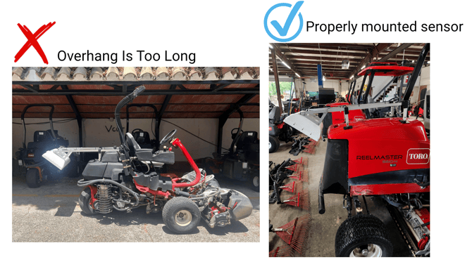
The goal is to keep the mount compact, support it over the strongest part of the mower cowling, and position the sensor at the intended measurement angle.
First: Keep the Mount as Horizontal as Possible.
This ensures that the sensor is mounted at the proper angle. The Universal Mount is designed so that the sensor measures toward the ground at approximately a 40° angle when the side tubes are horizontal.
Most mower models require some adjustment to achieve this position. Depending on the shape of the mower cowling, the mounting legs may need to be adjusted, or the side tubes may need to be shortened.
Minor variations from the intended angle (±5°) do not affect the readings, but if the sensor is mounted at a different angle, then this has to be accounted for by tuning. In general, the mount should be installed as close to the intended geometry as possible.
Best practice: Adjust the mount, particularly the adjustable front leg height, so the side tubes are as close to horizontal as possible before finalizing the installation.
Second: Keep the Sensor Close to the Mounting Legs.
Avoid positioning the sensor too far off the back of the mower. If the sensor extends more than approximately 10–20 cm (4–8 in) beyond the rear of the mower, cut the side tubes where thez connect to the rear legs, with an angle grinder or saw, to bring the sensor closer to the mounting structure. A sensor mounted far away from the supporting legs acts like a long lever. Movement and vibration of the sensor creates much larger forces on the front legs and on the mower cowling.
Best practice: Keep the sensor as close as practical to the supporting legs rather than extending it unnecessarily behind the mower.
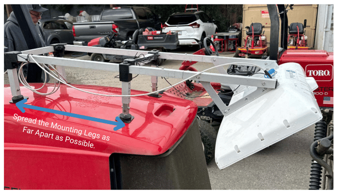
Third: Spread the Mounting Legs as Far Apart as Possible.
The front and rear mounting legs should be positioned as far apart as the mower allows. Increasing the distance between the mounting points provides a more stable base for the sensor and reduces the force transferred onto the mower cowling. On many triplex mowers, this means fully extending the front legs and modifying (shortening) the side tubes accordingly.
Best practice: Maximize the distance between the front and rear mounting legs while keeping the overall mount compact.
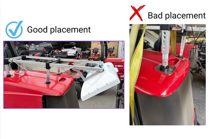
Before positioning the front mounting legs, check how the mower cowling is supported.On some mower models, the upper cowling extends beyond the supported or vented rear section. This creates an overhanging area that should not be used as the primary support point for the mount. For these machines, install the front legs behind the unsupported overhanging section. This is particularly important on mower designs such as older Toro Reelmaster 5010-H models.
Best practice: Place the mounting legs over supported sections of the mower cowling rather than on unsupported overhangs.
Fifth: Trim the Side Tubes When Necessary.
Some mower installations will require cutting of the side tubes. Do not leave the side tubes longer simply because the mount can physically be installed that way. Excess tube length moves the sensor farther away from the supporting legs and increases the leverage acting on the mower cowling.
When trimming the mount:
- Position the front and rear legs as far apart as practical.
- Determine the shortest suitable side-tube length by positioning the sensor as close to the supporting legs as possible while leaving 10-20 cm (4-8 in) clearance from the rear of the machine.
- Trim the aluminum tubes equally with an angle grinder or saw, removing length from the end that attaches to the rear leg.
- Adjust the front leg height such that the side tubes are approximately horizontal.
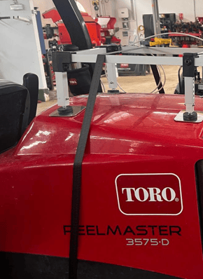
Sixth: Place the Security Strap over the Rear Legs.
The adhesive on the steel plates is strong once set after 24 hours, however we still recommend attaching the provided strap for additional safety against accidental detachment of the sensor or failure of the magnets. Whenever possible, the strap should be placed over the side tubes, near the rear legs of the universal mount, to avoid additional force on the front legs. The majority of the upwards force will be at the rear legs.
Seventh: Assign the Correct Area Types for the Sensor.
Assign the sensor to measure only on the desired area types based on where that particular mowers / sensor will be used. Read more about how to select area types here: Hardware & Data Uploading Status
Key Takeaway:
For a stable and reliable Universal Mount installation:
- Keep the side tubes as close to horizontal as possible.
- Keep the sensor close to the front legs of the universal mount and spread the front and rear legs as far as possible.
- Avoid allowing the sensor to extend more than approximately 10–20 cm (4–8 in) beyond the rear of the mower.
- Do not hesitate to trim the side tubes when necessary rather than creating unnecessary pressure on the mower cowling.
- Mount the legs on securely supported (non-overhanging) sections of the mower cowling.
- Attach the security strap over the side tubes close to the rear legs.
- Select sensor area types based on where the mower will be used / intended to measure.