![turfrad_logo_outlines (1)-1.svg]](https://support.turfrad.com/hubfs/turfrad_logo_outlines%20(1)-1.svg)
Table of Contents
This manual will guide you step by step through the assembly and set-up of your turfRad Toro Array Mount. It is structured in 5 sections:
-
1. Assembly Mount
-
Installation of the Sensors
-
Wiring to your Workman
-
Operations with Array Mounted Sensors
-
Live Path
Care and Maintenance
-
Clean the powder coated sheet metal and L-profiles with a damp cloth or lowpressure hose. Avoid harsh chemicals and abrasive cleaners.
-
Touch up all scratches and chips in the powder coating immediately using metal primer. Bare metal exposed by scratches will rust quickly, especially in outdoor and wet conditions.
-
The sidebar pivot uses a bronze oil-embedded bearing — it is self-lubricating and requires no greasing under normal use. If the pivot becomes stiff or squeaky, apply a small amount of light machine oil.
-
Inspect all screws and locknuts periodically and re-tighten as needed. Do not over-torque — tighten firmly by hand with the supplied allen key.
-
In high-vibration environments, apply medium-strength thread-locking compound (e.g. Loctite 243) to prevent screws from loosening over time.
-
If the sensor is malfunctioning, consult your local distributor or visit https://support.turfrad.com/.
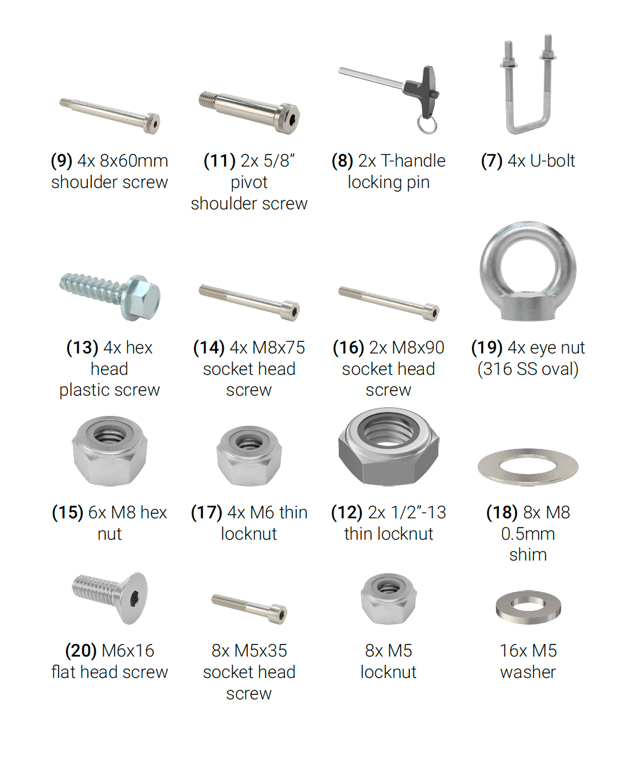
What's in the box
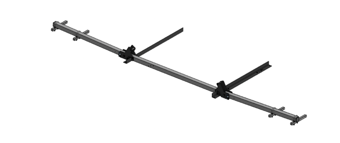
 Assembly Mount
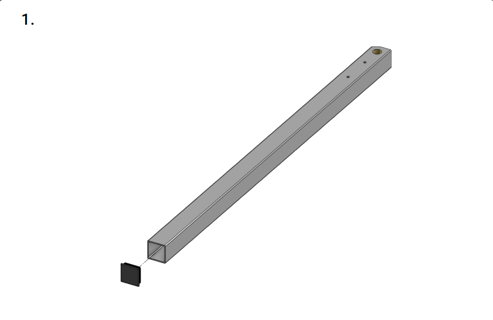
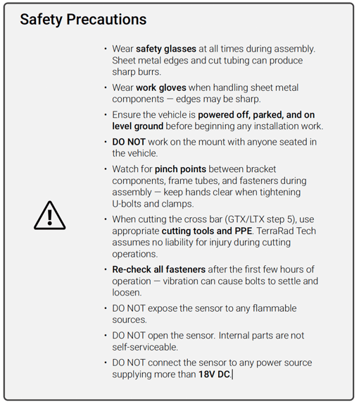
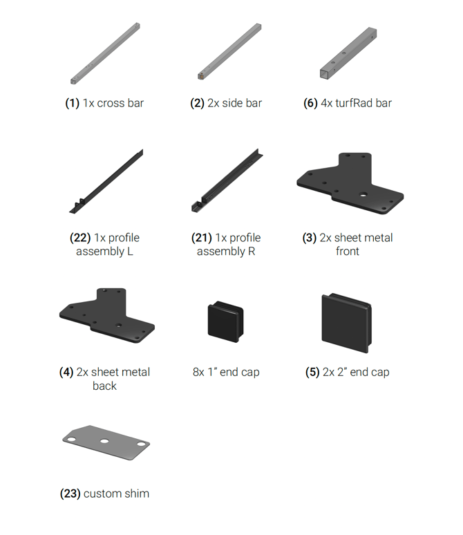
Insert the 2” end cap (5) into each end of both sidebars (2). Press firmly until each cap seats flush. The cap should sit level with the tube end with no gap.
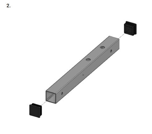
Insert a 1” end cap into each open end of all four turfRad bars (6). Press firmly until each cap seats flush. A rubber mallet can help if the fit is tight — do not use a metal hammer directly on the cap.
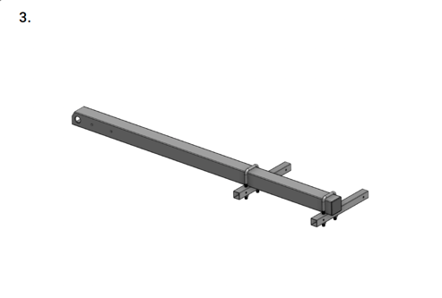
Slide each turfRad bar (6) into position on the sidebar and secure with a U-bolt (7). Do not fully tighten at this stage — bars will be aligned and tightened in a later step. Ensure the U-bolt saddle sits flat against the tube before snugging.
Workman MDX
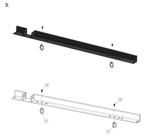
Install an M6x16 screw and an oval eye nut (19) onto each L-profile assembly (21, 22), one on the left side and one on the right side. Orient the eye nut with the oval opening facing outward as shown. Tighten securely with the supplied allen key.
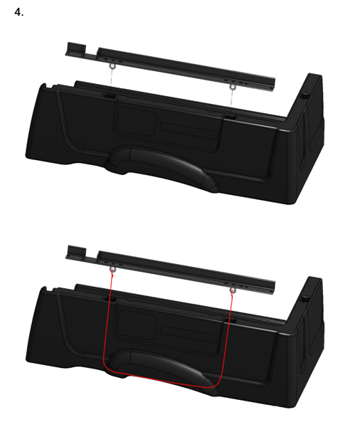
Place the ratchet strap hooks onto the eye nuts. Insert each hook from below the MDX bed and fish it up through the hole, then hook it onto the eye nut. Tighten the loose strap ends below the bed using the ratchet until the mount sits firm and level. Do this for both sides.
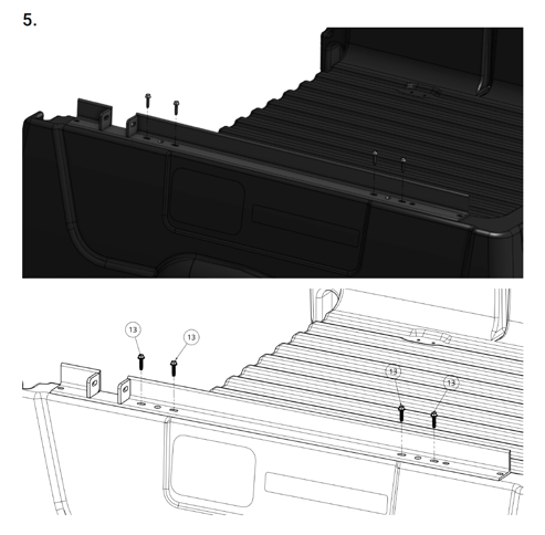
Attach a ratchet strap to the eye nuts on both L-profiles and routeit along the side of the MDX as shown. Then insert the plastic hex screws (13) at the locations shown. Do not over-torque — tighten firmly by hand only. Over-tightening will strip the plastic threads and the hole can no longer be used with this screw.
Workman GTX / LTX
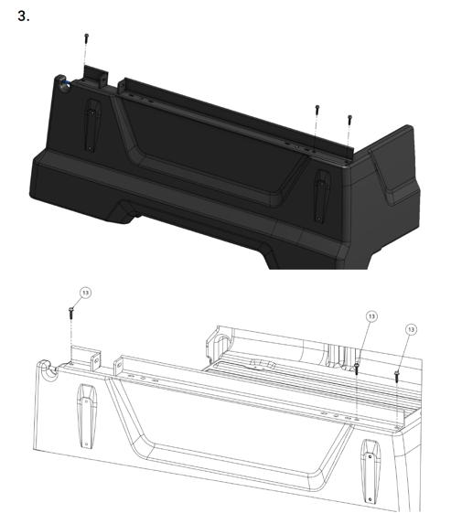
Position the mount structure on the GTX/LTX bed and secure it using the provided screws at the locations shown. Ensure the mount sits flat on the bed surface before tightening. Do not over torque— tighten firmly by hand only.
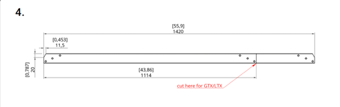
Cut the cross bar (1) to a length of 1114mm at the marked location. Then cut the chamfer as shown: 20x11mm. Warning: TerraRad Tech assumes no liability for injury during this step. Use proper safety equipment and appropriate cutting tools at all times.
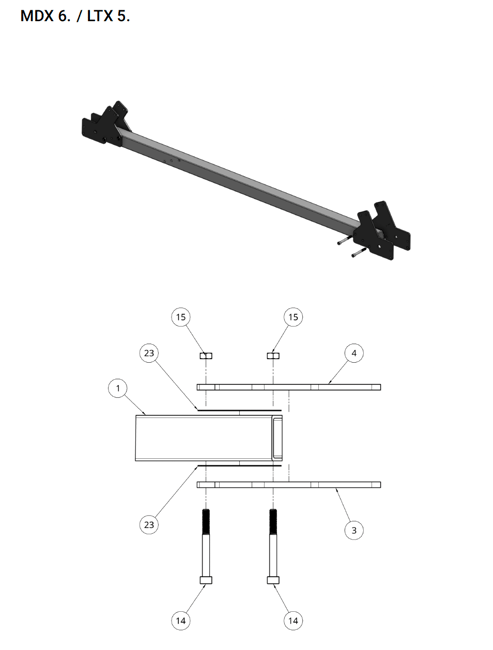
Assemble the cross bar (1) with a sheet metal front (3) and sheet metal back (4) on both ends. Secure each end with two M8x75 socket head screws (14) and M8 hex nuts (15). Important: Do not forget to place the custom shims (18) between the sheet metal and the cross bar as shown. Tighten in a cross pattern so both sheet metal pieces clamp evenly. Do this for both sides. Make sure the countersink holes of the sheet metal back are on the inside facing the cross bar.
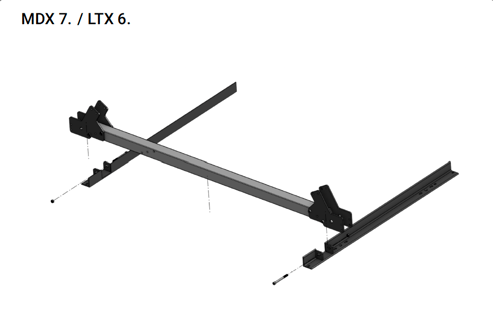
Lower the assembled cross bar onto the installed L-profiles on the Workman and align the mounting holes. Secure with M8x90 socket head screws (16) and M8 hex nuts (15). Use additional shims (18) if needed to ensure the cross bar sits level. Visually check from the front that the cross bar is parallel to the ground before fully tightening.
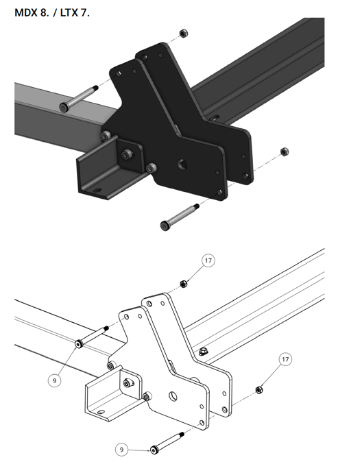
Insert the 8x60mm shoulder screws (9) into the designated holes as shown. Tighten securely. The shoulder (unthreaded section) must pass fully through the bracket so the screw seats on its shoulder, not the thread.
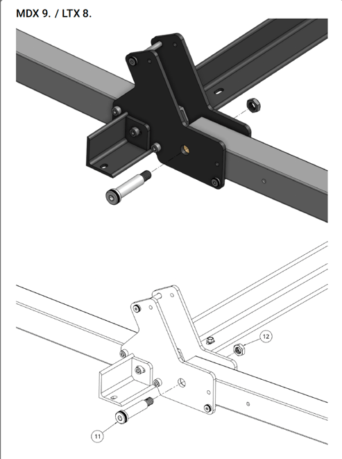
Attach the sidebar assembly using the 5/8” pivot shoulder screw (11) and 1/2”-13 thin locknut (12). Tighten firmly, but confirm the sidebar still pivots freely — this screw acts as the rotation axis.
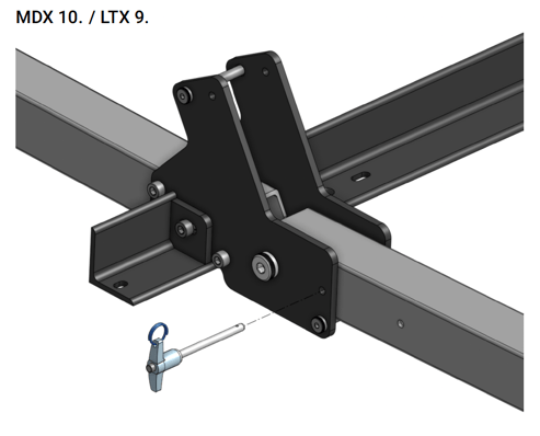
Insert the T-handle locking pin (8) to lock the sidebar in position. The mount is now fully assembled. Proceed to install the turfRad sensors and wiring.
Installation of the Sensors
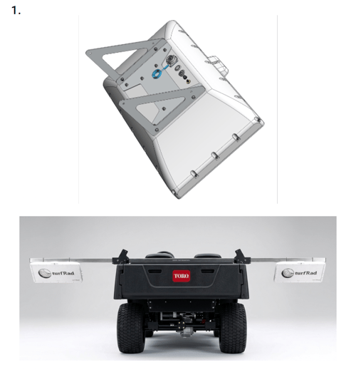
Mount the turfRad sensors onto the turfRad bars using the triangular brackets included with each sensor. First attach the brackets to the sensor with the provided M5x12mm screws, washers and M5 locknuts. Then mount the sensor assembly onto the turfRad bars using the M5x35mm socket head screws with the corresponding washers and locknuts. Adjust the U-bolts so that the edge of the sensor sits flush with the end of the sidebar — this positions the sidebar as a protective guard for the sensor.
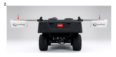
Attach the GPS antennas to the sidebar at the locations shown using zip ties. Ensure each antenna faces upward. Route the zip tie around the black antenna body — not around the cable.
Warning:
-
The GPS cable is very delicate. If it is pinched or kinked it will break and must be replaced.
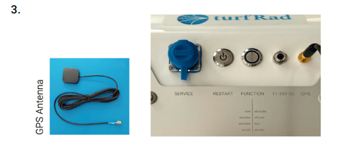
Place the GPS antenna as shown in step 2 above. Then connect the black wire to the gold GPS connector.
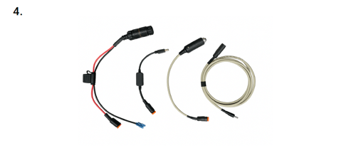
Choose the desired power cable for your setup. We recommend using the direct wiring dongle for maximum reliability. Alternatively, you can use the cigarette lighter plug or the USB Dongle. Be aware that when using the USB dongle, the USB port must be rated for 5V 2A. If using the cigarette lighter plug, ensure it works reliably and doesn’t easily lose power from vibrations (check green LED on the plug). Note: We do not recommend using the cigarette lighter plug in non-locking receptacles.
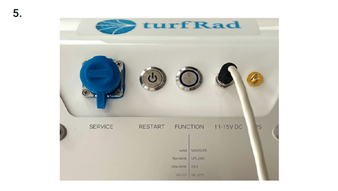
First, make sure the vehicle is powered off and it is safe to connect the power cable. Next, connect the power cable to your vehicle. Now connect the other end to the 11-15V DC port of the turfRad sensor. Make sure the plug is fully inserted and screwed on tightly.
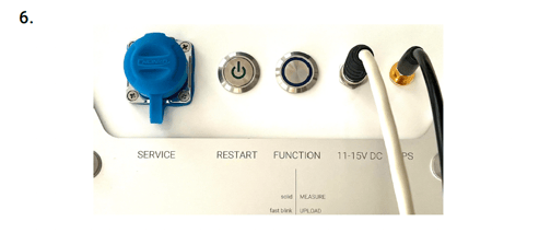
The image above shows the connected power cable and GPS antenna. When you power on your vehicle, the LED on the RESTART button should now turn on. As soon as the GPS signal is found, the blue LED on the FUNCTION button will start to blink slowly (once per second). Note that this can take several minutes and requires a clear view of the sky.
Wiring to your Workman
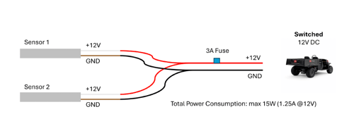
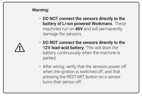
Wire both sensors directly to a switched 12V DC power port on the Workman. Depending on your model, this port is typically found under the seat or behind the console (e.g. behind the USB outlet or the wireless hour meter). If you are unsure of the location, ask your distributor. Make sure the machine is powered off before starting. Connect the wiring harness to the 12V power port and install a 3A fuse on the positive line. Ensure you connect the +12V and GND terminals correctly as shown. Then split the power for both sensors using the provided wiring harness or a suitable connector (e.g. Wago lever-nut). Each sensor draws a maximum of 7.5W, so the total maximum power consumption is 15W (1.25A @ 12V).
Note: The sensor power cable has two leads: the white wire is +12V and the brown wire is GND.